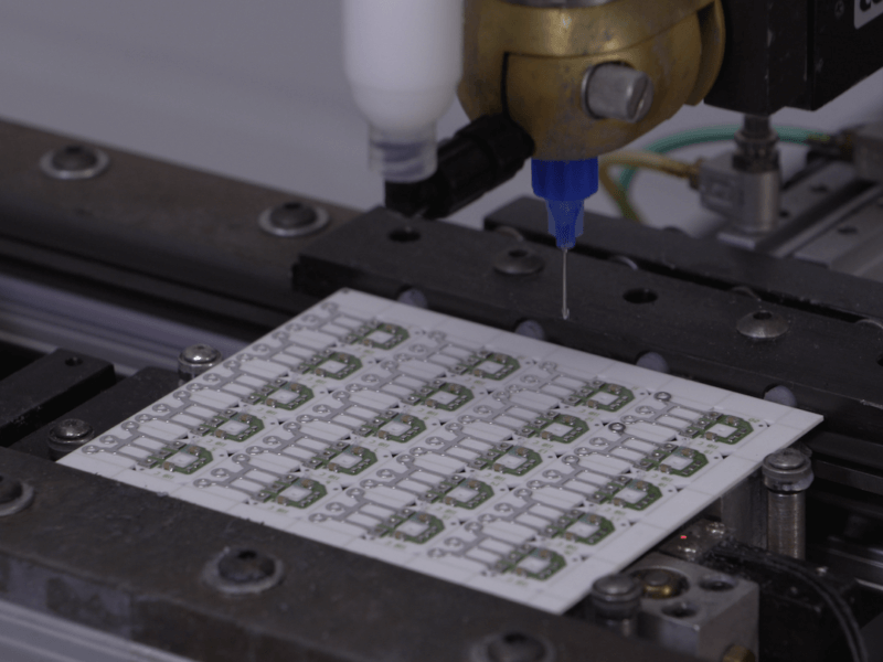
Vehicles are a challenging place in which to deploy electronics. High temperatures, coupled with vibration and the potential for humidity, shorten the life of circuit boards made from FR4 (the epoxy-impregnated fiberglass laminate material used in computers and elsewhere.) To maximize reliability, durability and performance Wells Engineered Products uses ceramic substrates rather than FR4 for high power applications.
These ceramic-based products are referred to as, “thick film hybrid circuits.” For engineers unfamiliar with how these are made, and for anyone interested in how high levels of consistency are maintained, here’s an overview.
Introduction to Thick Film Hybrid Circuits
The fundamental difference between thick film and other circuits is the height of the electrically conductive metal traces screen printed onto the substrate. Thick film circuits produced by Wells are up to 25 μm (0.001”) thick whereas thin film circuits are no more than 2 μm (0.0001”) thick. The increased cross-section lowers resistance, enabling higher power levels with less heating.
Thick film circuits are applied to both FR4 and ceramic substrates. Alumina-based ceramic substrates are more rigid than FR4 and have higher thermal conductivity. This prevents hot spots forming in high power and/or high heat applications.
There is a difference in the inks used with these substrates. For the thick film FR4 circuit boards that Wells manufactures these are a silver-based polymer ink. Ceramic substrates however use a platinum-silver mix which adheres strongly to the ceramic while providing the electrical conductivity required.
After printing a non-conductive material is applied over the circuit. It’s possible to print another circuit layer on top of this, which raises utilization of the ceramic substrate and keeps the device compact. Many thick film circuits are composed of multiple layers: at Wells, depending on the type of device and its size, there can be up to 11 in total.
The “hybrid” aspect of these circuits refers to the electrical components incorporated into them. Resistors are produced as part of the printing process while other devices are mounted on the ceramic and electrically bonded to the platinum-silver traces.
Manufacturing Thick Film Circuits
The principal steps are:
- Screen-printing
- Drying and baking
- Laser trimming
- Surface mount of components
- Inspection
Screen-Printing
Electrical traces are formed by screen-printing platinum-silver ink onto the substrate. The screens themselves are produced by a photomasking technique where exposure to UV light selectively hardens coated regions. Washing then removes the uncured material, leaving “holes” where the screen print machine squeegee pushes the ink through and onto the ceramic.
Drying and Baking
Thick film circuits screen-printed onto ceramic are then dried in an oven at 200°C before being baked at around 850°C. Additional layers are added by making repeat passes through the printing, drying and baking processes.
Laser Trimming
One feature of thick film circuit manufacturing is the ability to “print” resistors along with the electrical traces. However, screen printed resistors exhibit variability of up to +/-20% from the target or nominal resistance. If not addressed this would lead to part-to-part variation that would create performance problems in the vehicle application. To avoid this, thick film circuits go through a laser trimming process.
In laser trimming each resistor is probed to measure its actual resistance. If below the nominal or target value a laser then selectively removes metal to reduce the area through which current flows, thereby increasing the resistance.
Laser trimming can reduce variability to better than +/-1%. It does however require sophisticated automated equipment capable of very high precision.
Inspection
Any defect in the printed wire traces may affect how the final product performs in service and will almost certainly shorten its life. To prevent this, every assembled thick film circuit is inspected under high magnification to find defects such as opens, shorts, voids and bleeding of overglaze.
Surface Mount of Components
Most electronic devices, both ceramic and FR4-based, need various components mounting on the substrate. Oil pressure sensors for example have a die attached to the board. These are installed and bonded in position byautomated machines capable of high throughput rates.
Applications for Thick Film Circuits
In a growing number of automotive applications increasing power levels require the use of thick film manufacturing processes. In addition, the superior heat transfer characteristics of ceramics ensures higher reliability and longer life. This makes any application with significant power and/or heat generation a good candidate. Voltage regulators are a prime example, as are oil pressure sensors. And with underhood temperatures rising, the need for ceramic thick film circuits is only going to keep growing.
A second reason for adopting ceramic thick film circuits is their superior tolerance to vibration. FR4 circuit boards can flex under such conditions, which leads to broken joints. The higher rigidity of ceramic ensures this won’t happen in devices using thick film circuits.
Depend on Thick Film Circuits in Challenging Environments
Wells Engineered Products prints millions of circuits each year for products delivered to the most demanding OE customers. Advanced design technology coupled with highly automated manufacturing yields durable, long-lasting electronic devices with predictable performance. This reduces the risk of warranty claims, and of greater importance, helps boost a reputation for quality products.
