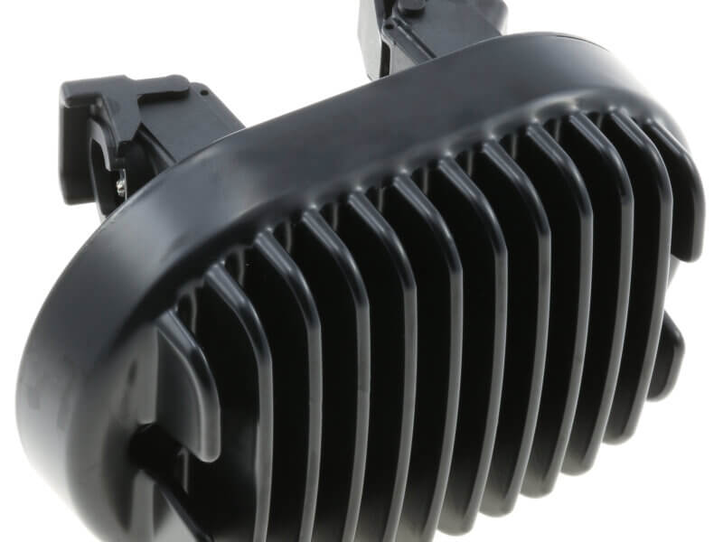
Reliability is top-of-mind for most vehicle buyers, and manufacturers striving to climb the dependability rankings look for ways to eliminate every possible problem. Electrical shorts and voltage regulator faults, though uncommon, can have expensive consequences, so it pays to explore designs providing higher levels of protection.
Modern voltage regulators use solid-state electronics to rectify and control AC electrical current from the alternator. Many manufacturers use a combination of silicon-controlled rectifiers (SCRs) and diodes. This blog post explains the advantages of an all-SCR approach.
Introduction to Electronic Voltage Regulators
The voltage regulator puts the output from the alternator into a form that can be used by the vehicle’s electrical and electronic systems. Understanding how it works, and hence the function of SCRs and diodes, requires an appreciation of alternator functions.
An alternator is about as pure an application of Faraday’s Law of Induction as you’ll find anywhere. An engine-driven pulley on one end of a shaft moves copper windings through a magnetic field to generate AC current. Higher engine speeds increase the frequency of that waveform, while field strength and rotation speed change its amplitude. These are problems because battery charging and other systems need a stable DC supply, nominally of 12V.
Voltage regulators achieve this by converting (“rectifying”) AC to DC and controlling the direction of current to regulate voltage. These functions are achieved through two components: a rectifier bridge and control circuitry.
The Rectifier Bridge
Rectification from sinusoidal AC to DC is done by switching. Essentially, circuits are switched off for the negative portion of the AC wave. If the alternator put out only a single AC wave, this would result in a sawtooth DC waveform. However, alternators generate three phases of AC output, each offset by 120°. Thus, by switching each phase independently, it’s possible to create a good approximation of stable DC electrical current.
In modern, solid-state voltage regulators, this switching is performed by semiconductor electronics. Some designs use a combination of diodes and SCRs, while others use SCRs only.
Circuitry for Voltage Regulation
The other function of the voltage regulator is to ensure the DC output is nominally 12V. (In practice, the target is usually around 13.5V.) This is achieved by controlling the SCRs to conduct phase current to the battery or short a phase or phases to ground. Conducting current to the battery will increase battery voltage. Shorting a phase to the ground will reduce battery voltage. The actual voltage generated is continuously compared with a reference voltage. The difference between the two is used to drive a feedback loop that increases or decreases the SCR conduction time.
Current Switching Technology
The two devices used to rectify AC into DC are diodes and SCRs. A diode is a one-way or non-return valve: it lets current flow in one direction but blocks it in the other. Inserted into an AC system, this will block 50% of each cycle.
An SCR is a form of controllable diode. Part of the thyristor family of solid-state devices, its blocking function can be turned on and off by a third control line connected to the “gate” on the SCR. Varying the width of this pulse enables control of both AC rectification and voltage regulation.
Two Designs of Voltage Regulators
Each phase coming from the alternator needs rectifying and voltage regulation control. This can be achieved with a diode and an SCR. The diode prevents current flowing in one direction while the SCR provides voltage regulation control.
An alternative is to use two SCRs per phase, which provides a higher level of control. Each approach has advantages and limitations.
Pros and Cons of 3 SCR, 3 Diode Designs
Eliminating three control lines to three SCRs reduces complexity. Costs are lower, primarily because SCRs are more expensive than diodes and also by virtue of the simplified design. An SCR is larger than an equivalent diode, so incorporating the latter potentially results in a more compact voltage regulator.
When considering safety and reliability, with this design, the SCRs protect against a phase being shorted to the ground. Although it’s a less common event, the design does not protect against a short to the battery.
Benefits of 6 SCR Designs
The primary reasons for using this approach are that it provides improved control over rectification and field current and adds additional protection against a short to battery. This helps improve the safety and reliability of other vehicle electronic systems.
Another consideration is that, unlike diodes, SCRs are engineered to handle higher power levels and generate less heat. As such, they are more efficient and reduce requirements for thermal management.
Choosing a Design Approach
Unlike some aspects of vehicle electronics, there are no industry standards or regulations dictating SCR versus diode usage, and most OEMs have their own preferences. Consequently, it’s often left to the individual engineer or engineering team to determine which approach will best satisfy their design goals.
The main considerations are cost and the level of electrical protection needed, and to a lesser extent, providing appropriate thermal management. In assessing protection needs, it’s essential to evaluate the likelihood of a phase short to battery, which is dictated by individual component, system and vehicle designs.
Get Support From Wells Engineered Products
Wells is a leader in the design and manufacture of electronic and electromechanical devices for the automotive industry. With headquarters and engineering in Fond du Lac, Wisconsin, our proximity to automotive OEM and Tier 1 manufacturers helps us provide exceptional levels of technical support.
Whether you’re engineering a new alternator or need dependable electronic and electromechanical components for other engine or vehicle applications, our expertise can help lower costs and improve performance and reliability. Contact us to learn more.
